Address
Busubait Fiberglass Factory
P.O Box 63113, Dammam 31516
Kingdom of Saudi Arabia
Work Hours
Monday to Friday: 7AM - 7PM
Weekend: 10AM - 5PM
Address
Busubait Fiberglass Factory
P.O Box 63113, Dammam 31516
Kingdom of Saudi Arabia
Work Hours
Monday to Friday: 7AM - 7PM
Weekend: 10AM - 5PM

Regular inspection helps identify cracks, leakage, support problems, and chemical damage before they become larger failures. This guide explains what to check and how FRP repairs should be planned.
Busubait Insights · Industrial fume control
Industrial fumes do not become an exhaust-control problem only when they reach a scrubber. Control starts at the point where contaminated gas, vapour, mist or air leaves the industrial process.
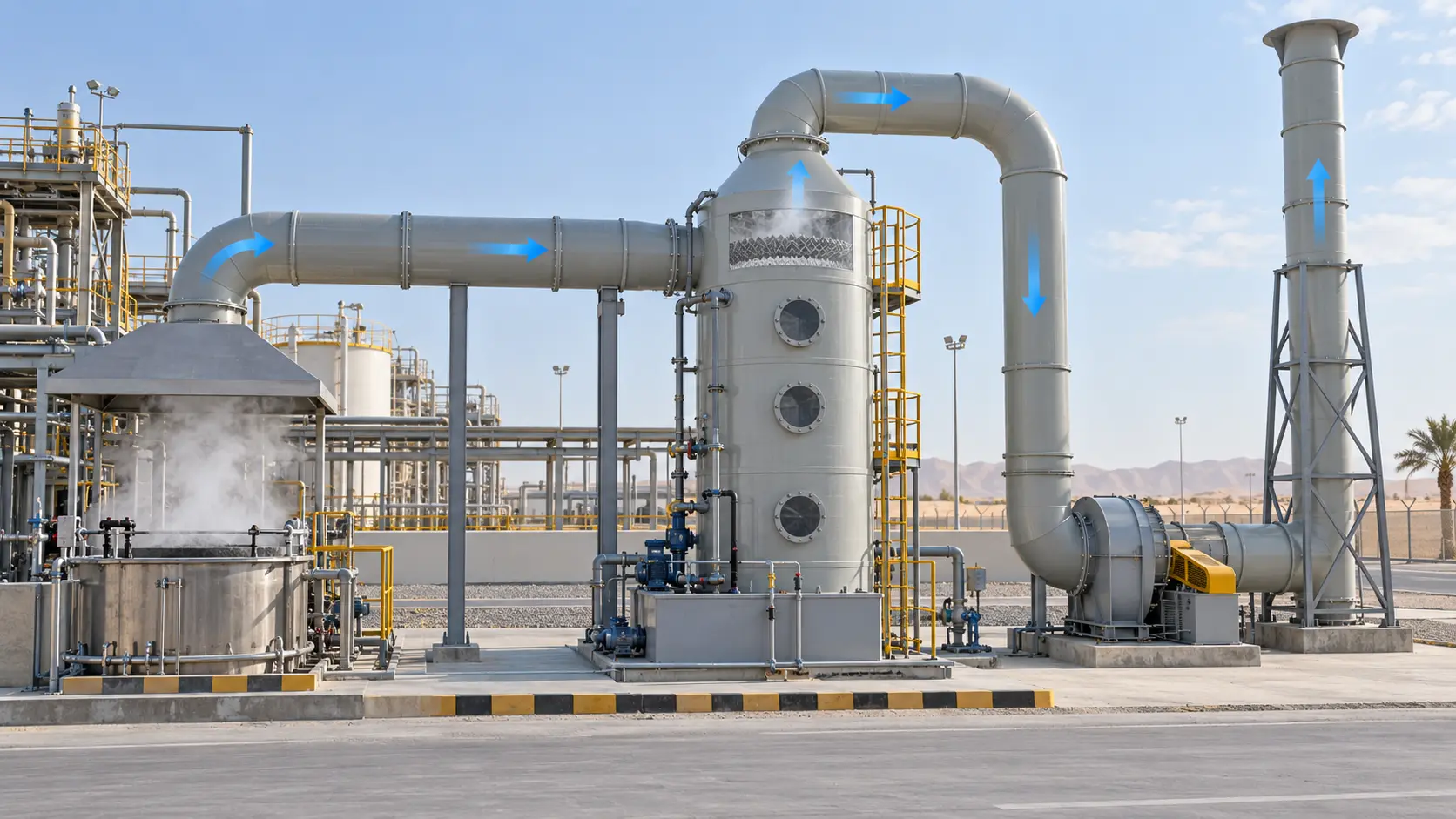
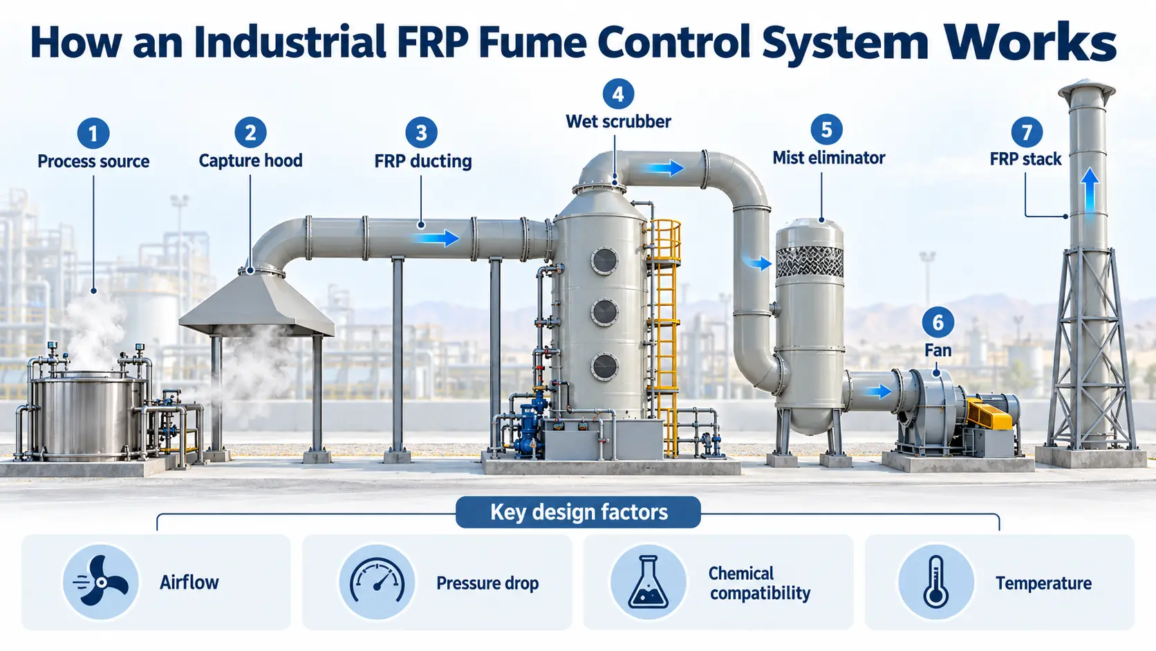
A complete industrial fume control system may include a capture hood, FRP ducting, scrubber, mist eliminator, exhaust fan and FRP stack. Each component has a different job, but they all need to work as one connected system.
A problem with capture airflow, duct sizing, pressure drop or material compatibility can affect everything downstream.
So, how does the complete system work?
Industrial fumes can come from chemical storage, manufacturing and treatment processes. Their composition varies depending on the chemicals being handled, process temperature, moisture and operating conditions.
Common sources include:
The exhaust stream may contain gases, vapours, acid mist, moisture, particles or a combination of these.
Some gases can also form corrosive condensate as they cool inside the exhaust system.
This is why system design cannot be based on airflow alone. Engineers first need to understand what is being released, how much is being released and under what process conditions.
The first job of an industrial fume control system is to capture contaminants before they spread through the surrounding work area.
A capture hood or enclosure is positioned close to the emission source. The hood draws contaminated air into the exhaust system before the fumes disperse.
Its effectiveness depends on factors such as:
Hood design also affects the rest of the system.
If the hood requires higher airflow, the ducting, scrubber, mist eliminator, fan and stack must be able to handle that airflow.
A poorly positioned hood cannot usually be corrected simply by installing a larger scrubber farther downstream.
Once the contaminant enters the hood, the ducting becomes responsible for carrying it toward the treatment equipment.
The ductwork between the emission source and scrubber can be exposed to untreated contaminants, moisture and corrosive condensate.
This is why Fiberglass Reinforced Plastic, or FRP, is commonly considered for corrosive industrial exhaust applications.
Busubait manufactures FRP ducting systems in round, rectangular and custom configurations for chemical and industrial applications.
However, selecting FRP is only one part of duct design.
Engineers also need to consider:
Every bend, transition and fitting creates resistance.
An undersized duct can increase air velocity and pressure loss. Poorly balanced branches can also result in some capture points receiving less extraction than required.
The chemical conditions inside a duct can change when the exhaust gas cools.
Moisture may condense on the internal surface and create a liquid chemical environment that is different from the original gas-phase conditions.
For example, a gas stream that appears relatively manageable in dry conditions may become much more corrosive once moisture and chemical vapours form condensate.
Material selection should therefore consider:
The practical lesson is simple. Airflow design and corrosion resistance need to be considered together.
After travelling through the ducting, the contaminated exhaust reaches the pollution-control equipment.
For many soluble industrial gases, treatment may involve a wet packed-bed scrubber.
Inside a packed-bed scrubber, contaminated gas moves through packing that provides a large wetted surface area. Scrubbing liquid flows across this packing, allowing targeted pollutants to transfer from the gas stream into the liquid.
Depending on the contaminant, chemicals may also be added to the scrubbing liquid to support neutralisation or absorption.
The exact scrubber configuration should always depend on the process conditions.
Busubait supplies FRP scrubber systems for industrial applications where corrosion-resistant construction is required.
A scrubber should not be selected based only on vessel diameter or airflow.
Important design inputs include:
High particulate loading can also affect the suitability of a packed-bed configuration because excessive solids may cause fouling or plugging.
This is why one scrubber design cannot automatically be applied to every exhaust stream.
For a deeper explanation of this equipment, see why FRP scrubber systems are used in chemical fume control.
Wet scrubbing brings contaminated gas into direct contact with liquid.
Once the treatment process is complete, small liquid droplets may remain suspended in the outgoing gas stream.
These droplets can contain:
Allowing excessive liquid carryover into downstream equipment can contribute to corrosion, deposits and maintenance problems.
This is where the mist eliminator, also known as a demister, becomes important.
A mist eliminator separates entrained liquid droplets from the outgoing gas before it travels farther through the exhaust system.
Common arrangements may use mesh or vane-type separation depending on the droplet size, gas velocity and process conditions.
The two components perform different jobs.
The scrubber is designed to remove or react with targeted contaminants in the exhaust.
The mist eliminator primarily removes liquid droplets carried out of the wet treatment section.
Understanding this difference is important when diagnosing visible moisture, liquid carryover or downstream corrosion.
The fan or blower creates the airflow that moves contaminated air through the exhaust system.
Its job is not simply to move air through one length of duct.
The fan may need to overcome resistance through the entire route:
Each component introduces some pressure resistance.
This means fan selection should consider the total system pressure drop at the required airflow.
For example, if the scrubber creates more resistance than expected, airflow available at the capture hood may decrease.
Similarly, changing the duct routing or adding additional fittings after fan selection can change the system operating point.
Fan material selection also matters.
Depending on its position in the system, the fan may be exposed to:
The fan therefore needs to be considered as part of both the airflow design and the chemical environment.
Once the exhaust has been treated and liquid carryover has been controlled, it still needs a defined discharge route.
That is the job of the exhaust stack.
A stack carries the treated exhaust away from the equipment and releases it at an engineered discharge point.
The stack may also need to resist moisture, chemical traces and outdoor environmental exposure. FRP can therefore be considered where corrosion resistance is important.
But there is an important distinction.
The stack does not neutralise chemicals or remove contaminants in the way a scrubber does. Its role comes after treatment.
Stack design may need to consider:
Stack height and outlet configuration should be determined for the individual project and applicable environmental requirements rather than copied from another installation.
The easiest way to understand the system is to follow the airflow.
Each stage influences the next.
For example, increasing extraction airflow at the hood also increases the air volume passing through the ducting and scrubber.
That can affect:
Changing the scrubber configuration may alter system resistance. Changing duct routing can affect fan requirements. Changing the process chemistry may affect material selection throughout the system.
This is why fume-control equipment should be considered as one connected system instead of purchasing individual components first and trying to connect them later.
Busubait manufactures a range of FRP air pollution control equipment, including scrubbers, corrosion-resistant ducting, stacks, hoods and related exhaust-system components.
Reliable system design starts with accurate process information.
Before selecting equipment, engineers should normally establish the main operating conditions.
The expected exhaust volume should be identified for each capture point.
Multiple hoods or branches also need to be considered together so that the complete duct network can be properly balanced.
The system designer needs to understand which gases, vapours, particles or chemical mixtures will enter the exhaust.
The concentration may also vary between normal operation, start-up and upset conditions.
Both normal and maximum temperatures matter.
Temperature changes may affect FRP material selection and can also cause condensation inside the ducting.
The amount of moisture inside the gas stream should be considered together with the possibility of condensation.
Condensate may create a chemical environment that differs from the original exhaust gas.
Particles or solids can influence scrubber selection and maintenance requirements.
High solids loading may also contribute to deposits or plugging.
Pressure resistance through each part of the system should be considered when determining fan duty.
This includes the hood, ducting, bends, scrubber, mist eliminator, fan connections and stack.
The materials used throughout the system should be suitable for the actual chemicals, concentrations and temperatures involved.
Engineers should also consider how components will be inspected, cleaned and maintained after installation.
Good access is particularly important around scrubbers, mist eliminators, fans and duct sections where deposits or condensate may collect.
FRP is not one single material formulation.
Its performance depends on the resin system, corrosion barrier, reinforcement and, in some cases, an additional thermoplastic liner.
This means material selection should follow the actual chemical environment.
Important questions include:
A mixture of chemicals can create different exposure conditions from a single chemical.
Chemical compatibility may change significantly with concentration.
Normal process temperature is important, but start-up conditions and possible temperature excursions should also be considered.
Condensate can expose the internal laminate to a different chemical environment from the gas itself.
Oxidising service may place different demands on the resin or liner system.
Materials should also be checked against chemicals used during washing, dosing and maintenance.
For more aggressive applications, Busubait's FRP ducting systems can also incorporate dual-laminate construction using suitable thermoplastic liners for specific service conditions.
The key point is straightforward.
Busubait's Bee’ah project in Jubail provides a practical example of scrubber, ducting and stack equipment being used as part of one exhaust system.
The published project information identifies the service as flue gases and lists:
The project information also specifies a 3 mm vinyl ester liner with a polyester structural laminate.
Published equipment dimensions include:
| Equipment | Published Dimension |
|---|---|
| Scrubber | Ø5,000 mm × 13,710 mm HT |
| Ducting | Ø1,800 mm × 15,573 mm, as listed |
| Stack | Ø1,800 mm × 40,000 mm HT |
The importance of the example is not simply the size of the equipment.
It shows how the scrubber, connecting ductwork and stack can form related parts of the same industrial exhaust project.
The published project information does not state a pollutant-removal efficiency or final emissions result, so no performance figure should be assumed from the equipment details alone.
You can view the Bee’ah Thermal Capacity Expansion Project for additional project information.
Industrial fume control is more than selecting a scrubber.
The capture hood first needs to collect the fumes effectively. The FRP ducting needs to transport them without unacceptable pressure loss or material degradation. The scrubber has to match the contaminant and operating conditions.
After treatment, the mist eliminator needs to control liquid carryover. The fan has to maintain the required airflow through the resistance of the complete system. Finally, the FRP stack provides the engineered discharge route.
When these components are considered together, designers can work from one set of project conditions covering:
This reduces the risk of treating each component as an isolated item.
If you are planning a corrosive industrial exhaust or fume-control project, Busubait can review your process conditions, drawings and specifications to help determine suitable FRP fabrication requirements.
Discuss your FRP air pollution control requirements with Busubait.
Either arrangement may be used depending on the system design. The main requirement is maintaining the required airflow and pressure through the complete exhaust path. Fan material compatibility should also be checked if the fan is exposed to untreated fumes, moisture or corrosive chemicals.
Fan sizing starts with the required airflow and total system pressure resistance. Engineers normally consider losses through the capture hood, duct friction, bends, fittings, scrubber, mist eliminator, downstream ducting and stack. The required operating point is then checked against the fan performance curve.
Yes, multiple capture points may be connected to one treatment system when the duct branches and airflow are properly designed. Each hood still needs enough extraction airflow. Engineers should also check whether mixing different exhaust streams could create unwanted chemical reactions or other process hazards.
Corrosion is influenced by more than temperature. Moisture, acids, chlorides, chemical vapours and condensation can create aggressive conditions inside the duct. Material selection therefore needs to consider the complete gas and condensate chemistry.
Wet scrubbing systems generally require a method for controlling liquid droplets carried by the outgoing gas. The type and configuration of the mist eliminator depend on the scrubber design, gas velocity and droplet characteristics.
A scrubber is designed to remove or react with targeted contaminants in the gas stream. A mist eliminator mainly separates entrained liquid droplets after gas-liquid contact. They perform different functions within the same treatment system.
FRP can be suitable for applications where fumes, moisture and chemicals create corrosion concerns for conventional materials. Its suitability still depends on the selected resin system, laminate construction, temperature and actual chemical exposure.
Not automatically. Different parts of the system may experience different temperatures, chemical concentrations, moisture and mechanical loads. Resin and liner selection should therefore be checked against the service conditions for each component.
The stack provides the final engineered route for discharging treated exhaust. It does not replace the scrubber or remove contaminants itself. Stack height, outlet arrangement and discharge conditions should be determined according to the specific project and applicable requirements.
Useful project information includes the exhaust airflow, contaminant type and concentration, operating temperature, moisture content, particulate loading, required treatment conditions, chemical composition, available layout, drawings and applicable project specifications. Providing accurate process data helps the manufacturer evaluate suitable materials and fabrication requirements.
Discuss your scrubber, FRP ducting and stack requirements with Busubait.
Discuss Your Project on WhatsApp